
CHA/V 2.0 User Guide
IMPORTANT: read the safety note at the end of this document before connecting things to the 3.5mm jacks
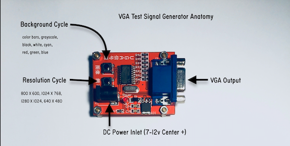
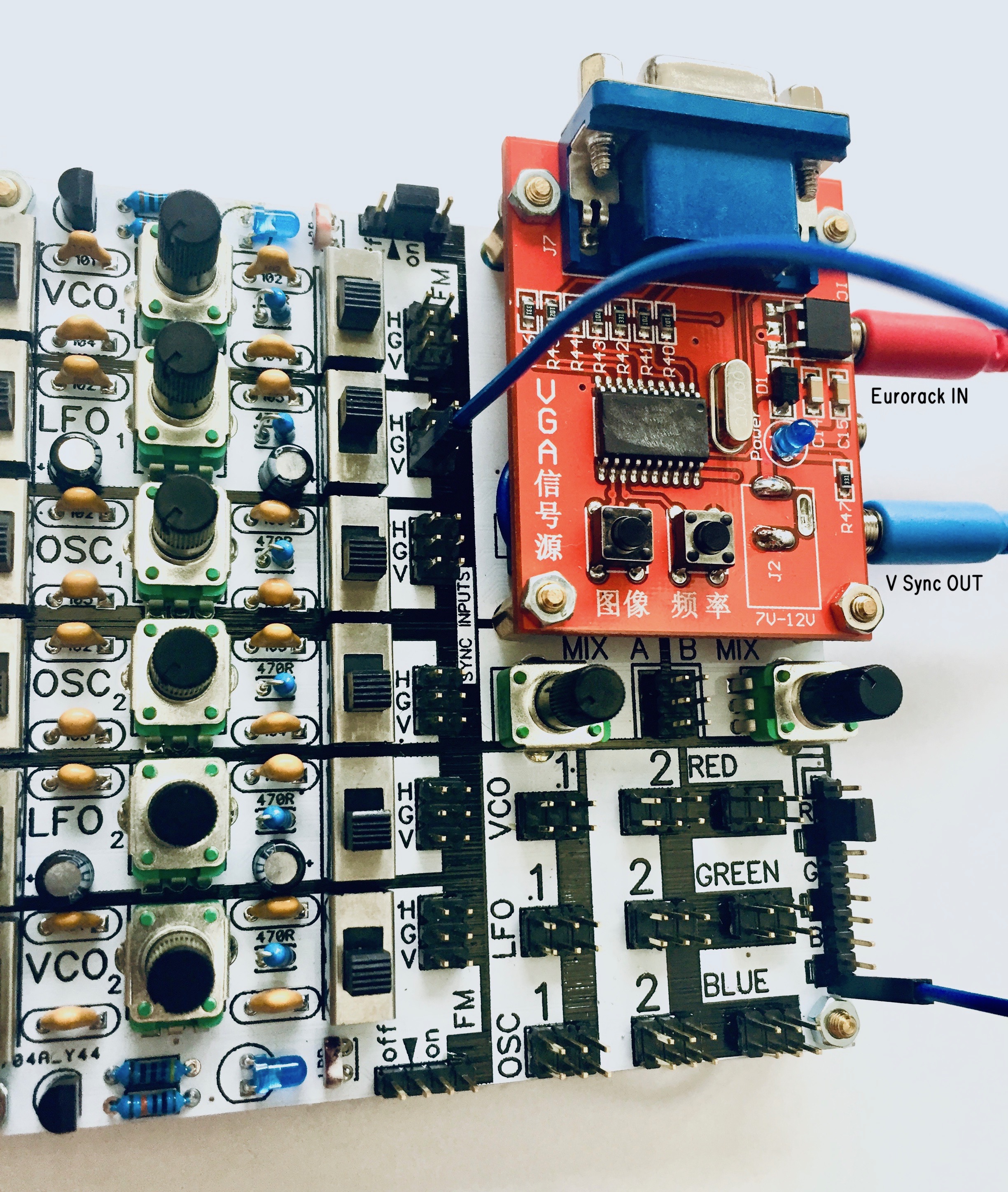
Congrats! If you made it here, you probably have a completed CHA/V that you’d like to test. Here’s a general overview of the controls:

To turn it on, plug in a 12v center-positive power supply. Center positive means that the sleeve of the jack is negative (in most cases it’s just ground) and the inside is the positive voltage. Anything above 500mA is more than adequate, and you can probably get away with even half of that.

dig through your box of old wall-warts and find a 12v one with this symbol, which means center positive.
If the power LED turns on and nothing starts smoking, you’re probably in business. If you have the CHA/V connected to a monitor with a VGA cable and you see color bars, you’ve passed the first test. Hit the background cycle button a few times and make sure it cycles though the colors. Hit the resolution cycle a few times and make sure it cycles through the resolutions.
All good? Cycle the background color to black.
Before any of the oscillators can be used, we’ll have to put in some jumpers. It’s doubtful any of them will do much without jumpers.
First, let’s look at the vactrol headers on the VCOs:
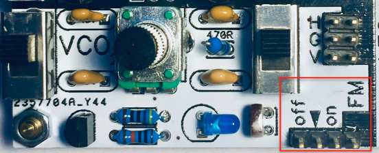
As-is, there’s no jumper, and because of that, the VCO circuit is not complete (it won’t do anything).
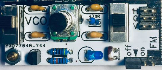
If you place a jumper connecting the [off] pin and the center-pin (the little triangle), the circuit will be complete, but the vactrol frequency modulation will be off. Here’s the off jumper position:
If you want frequency modulation to be on, place a jumper connecting [on] and the center pin. Like so:
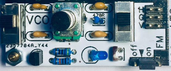
In this position, the LDR will be inserted into the VCO circuit and it (in addition to the potentiometer) will change the frequency of the VCO. Once we get this fired up, if you wave your hands around over it, it will change the amount of light that the LDR sees, and in turn change the frequency (pitch). For now, put the vactrol headers of both VCOs in [off] position.
Ok, now we have to place jumpers on all the sync headers. Each oscillator has a sync header like the one pictured below. They are all identical.
The pins on the right (in the red box) are the sync inputs for each oscillator. There are 3 pins, but you should only connect one of them at a time.

The pins along the left are:
horizontal video sync pulses from the VGA tester [H]
vertical sync pulses from the VGA tester [V]
ground [G] which allows the oscillator to free-run
In the picture below are some oscillators with jumpers in place:
OSC2 is synced to V
LFO2 is free-running (G)
VCO2 is synced to H
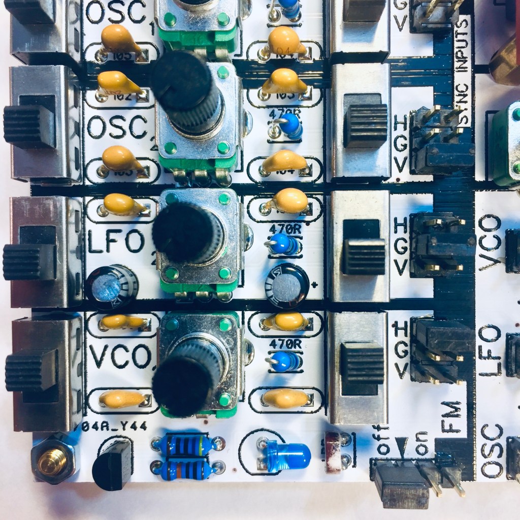
Initialize the CHA/V for some basic tests by setting the jumpers and switches like this:
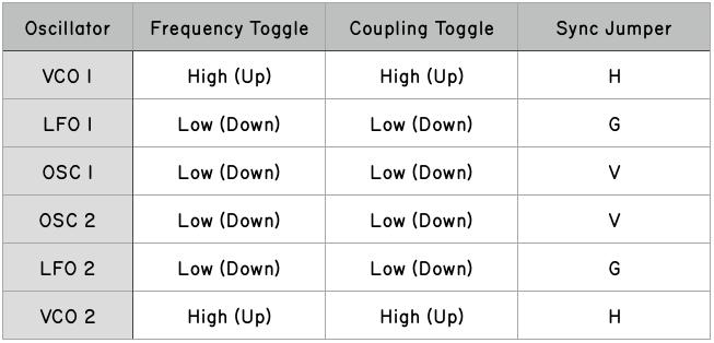
This is the most basic configuration. The VCOs should make vertical lines, the OSCs should make horizontal lines, and the LFOs are ready to animate the VCOs.
Something counterintuitive about video oscillators is that horizontally synced oscillators make vertical lines, and vice versa. I didn’t make this up, it’s just the way it is.
In the above configuration, here are the basic patches to start with:
VCO1 > RED, GREEN or BLUE = Vertical red, green or blue lines
OSC1 > RED, GREEN or BLUE = Horizontal red, green or blue lines
See what you can come up with just by patching both VCOs and OSCs to RED, GREEN and BLUE and playing with the frequencies. Because each oscillator has multiple outputs, and each color has multiple inputs, you can experiment with sending one oscillator to multiple colors, multiple oscillators to one color, or any combination. Play with the coupling toggle switches to change the line thickness. Some combinations will work as expected, and others will have unexpected results, especially when lots of oscillators or colors are patched together.
Using Sync Creatively
Using H, G, or V on an oscillator’s sync header is just the beginning. Try removing the sync jumper from an oscillator and syncing it with another oscillator’s output, like this:

In the picture above, OSC1 is synced to V, and OSC2 is synced to OSC1. The frequency of OSC2 will now be a division of OSC1. Changing the frequency of OSC1 will also change the frequency of OSC2. In order to see it, the oscillators would also need to be patched to colors. For example, patch OSC1 to RED, and OSC2 to BLUE, like in the picture below. This patch would make synchronized red and blue horizontal lines.

For further experimentation, try cascading the sync through multiple oscillators, syncing a slow oscillator with a fast one, or a fast one with a slow one. All sorts of unexpected and interesting artifacts can happen when the sync starts getting weird.
Frequency Modulation
Patch VCO1 to a color. Turn the VCO1 vactrol [on]. If you cover the LDR of VCO1 with your hand, now you should see the frequency change. Try shining a light on it.
Set LFO1 to free-running (G) and set its switches to low/low. Now patch LFO1 into the FM pin on the VCO1 vactrol header. The LED should now be flashing and animating VCO1.
Change the frequencies of LFO1 and VCO1 and watch what happens.
Try V, H and G modes for VCO1 with all the different combinations for the toggle switches. Some will be orderly, and some will be chaotic. Also try syncing LFO1 to V or H and see what happens.
3.5mm Jacks
The 3.5mm JACKS are intended to get signals (audio, video, sync, control voltages, etc) in or out of the CHA/V. By default, they don’t do anything. In order for a jack to do anything, one or both of its corresponding pins on the JACK HEADER have to be connected to something.
Here’s how the JACK HEADERS work:
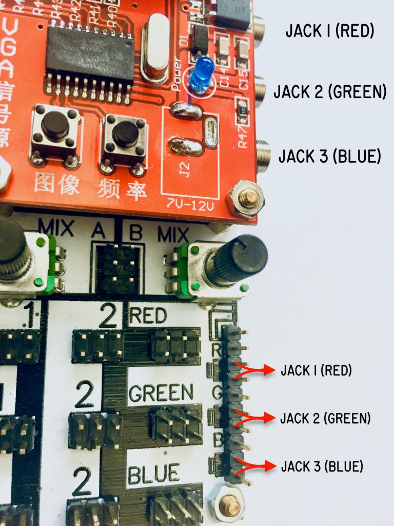
As the picture above illustrates, each jack has two pins on the header (the jack pins have a little picture of a jack next to them). Both pins for each jack are the same, and either can be used to patch a jack to something.
The R, G, and B pins on the JACK HEADER are just extra RED, GREEN, and BLUE inputs. They’re also connected directly to the VGA pins.
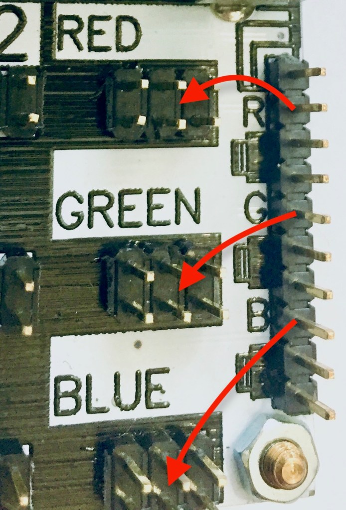
A default configuration for the R, G, and B pins on the JACK HEADER is for the convenient patch below:

Jack 1 is jumpered to R
Jack 2 is jumpered to G
Jack 3 is jumpered to B
This turns the CHA/V into a simple audiovisual synth. Any of the oscillators connected to:
RED can be heard via JACK 1
GREEN can be heard via JACK 2
BLUE can be heard via JACK 3
There’s an extra pin for each jack, so that the jacks can be jumpered to a color pin and patched to something else at the same time.
Keep in mind: horizontal lines are usually within audible range and vertical lines are usually too high frequency to hear.
In addition, you can send audio IN to the jacks. Any audio coming IN to:
JACK 1 will make RED lines
JACK 2 will make GREEN lines
JACK 3 will make BLUE lines
You can also use the jacks to patch composite video in, although it will scroll and glitch because the format is different (different sync and probably resolution too).
The jacks don’t necessarily have to be associated with a color, and they can be used for all sorts of other things if you remove the jumpers.
Other uses for the jacks:
- Use an external audio source to FM one of the VCOs

- Send an unused sync pin out one jack to sync a Eurorack oscillator, and bring the Eurorack oscillator output back into a color via a different jack.
IMPORTANT: It’s not advisable to connect an external source to the same color that an internal CHA/V oscillator is also connected to. More on this can be found at the end of this document in a section entitled “SAFETY”.
Mixers
MIX A and MIX B are nothing more than two separate patchable potentiometers. The six pins are just connected directly to the contacts of the two potentiometers as shown:
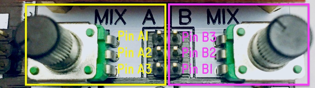
Although this is an incredibly simple “circuit”, having these two potentiometers adds a huge amount of creative potential to the CHA/V. Having patchable pots is also a fun way to build and experiment with some basic circuits from scratch. Here’s a cookbook using the pin names from the picture:
MIXER COOKBOOK
The examples use MIX A, but they can also be done on MIX B, as the two mixers are identical.
Variable resistor: Patch any oscillator output to pin A2. Patch pin A3 to a color. Adjusting the MIX A pot changes the brightness, but it will not be able to reduce the brightness to fully off.
Attenuator: Start with a variable resistor patch, and then patch an unused G pin to A1. Adjusting the MIX A pot changes the brightness from fully on to fully off. If audio output is being used, this will also act as a volume control for that color.
Another use for this patch is to control the FM depth of a VCO. Leave A1 connected to G, patch an LFO output to A2, and patch A3 to a VCO’s FM input (make sure FM is on). Adjusting the MIX A pot will alter the frequency modulation depth.
Crossfader: Patch the output of one oscillator to A1 and the output of another oscillator to A3. Patch A2 to a color. Adjusting MIX A will crossfade between the oscillators.
Color mixer: Patch any oscillator to A2. Patch A1 to a color. Patch A3 to a different color. Adjusting MIX A will blend the two colors. A fun way to experiment with RGB color mixing is making a patch that uses both mixers and all three colors.
VCO Fine Tune: Patch a VCO’s FM [off] pin to A1. Patch the FM pin with the little triangle pointer to A2. The idea is to replace the vactrol jumper with a variable resistor. Adjusting MIX A will fine tune the frequency of the VCO. Fine tune is really useful when a VCO is synced to H, but the frequency range is set to low.
Sync Router: Patch a V pin to A1. Patch an H pin to A3. Patch A2 to an oscillator’s sync input. Adjusting MIX A fades between vertical and horizontal sync. This actually shouldn’t work, but in the weird world of the CHA/V, it makes some strange sync distortion effects. Be advised, if you short V and H together, you’ll lose the video signal. You’ll also lose the signal if V or H get connected to G.
Dirty Mixer: You can patch Karl Klomp’s famous “non-sync dirty mixer” with the CHA/V. You’ll need three 3.5mm to RCA cables. Here’s how to do it: Patch A1 to JACK1, A2 to JACK2, and A3 to JACK3. Using your adapter cables, connect JACK1 to the output of a composite video source like a camera, VCR, or video mixer. Connect JACK3 to the output of a different composite video device. Connect JACK2 to a composite video monitor. Adjusting MIX A will crossfade between the two sources, and if they aren’t synced, all sorts of strange sync distortion things will happen, like scrolling and flickering. If you really want to make a mess, introduce some CHA/V oscillators (which REALLY won’t be synced) into the mix.
TIPS:
- Although all of the oscillators have specialties, all of them are able to produce relatively high or low frequencies. Try playing to their strengths, and also AGAINST them. The rules were made to be broken.
- Try leaving some jumpers off and see what happens when the oscillators “float”. You can also use your finger as a temporary jumper for sync or on the vactrol header.
- Change the resolution if something is acting weird or not synching the way you want it to. This sometimes fixes things. It also sometimes clears up weirdness that occurs along the edges of the screen.
- Change the background to white and all the colors will be inverted.
SAFETY
This is the “don’t cross the streams” clause.
With the 3.5mm jacks, it’s not advisable to connect an external source to the same color that an internal CHA/V oscillator is also connected to. For instance, if you had VCO1 patched to RED, I would advise that you do not patch one of your Eurorack oscillators to RED at the same time.
9/10 times this will probably be fine. I’ve tried various perfect-storm scenarios and haven’t been able to kill anything yet.
BUT because the CHA/V prioritizes cost above functionality, there isn’t any protection circuitry on the outputs, which could result in a murder/suicide scenario if the other device you’re playing with is also not made correctly. Many Eurorack and “boutique” synth devices that appear “professional” are actually made by idiots like me.
For those of you who are technically inclined, here’s why to not cross the streams:
- The CHA/V circuit is unipolar and unbuffered, so significant negative voltage from a bipolar oscillator could potentially damage the chips.
- In a doomsday failure scenario, the onboard oscillators could potentially output up to 12v.
Do what you want, but don’t say I didn’t warn you if a CHA/V sets your Monotron on fire and then explodes.
