
Bob Rall Mod
Bob Rall “Pro-Fifty” TBC proc amp mod for the Panasonic WJMX50 video mixer
If you just stumbled on to this page, these are instructions and documentation for adding proc-amp controls (brightness, contrast, hue, and saturation) to both channels of a Panasonic MX50 video mixer. Bob Rall devised these modifications, and offered them as a service throughout the late 90’s. Then he disappeared from the face of the earth, until 2018, when he emailed me! WHOA!!
Thanks to Benton C. Bainbridge for donating a modified MX50 and inadvertently making this possible.
Disclaimer: This documentation is untested and incomplete. It has been published for educational purposes only. If you break your stuff, it’s your own fault. Do not contact me with technical support questions for performing this modification. If you use this information for personal profit, you have to live with yourself and your bad karma. ALSO, according to Bob, after the proc amp mods have been implemented, the entire mixer will need to be recalibrated.
UPDATE: contrast mod successfully replicated.
UPDATE UPDATE (9/2018): digital shield daughterboard mystery solved by none other than Bob Rall himself! Documentation here.
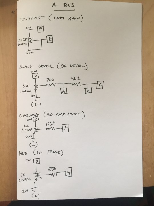
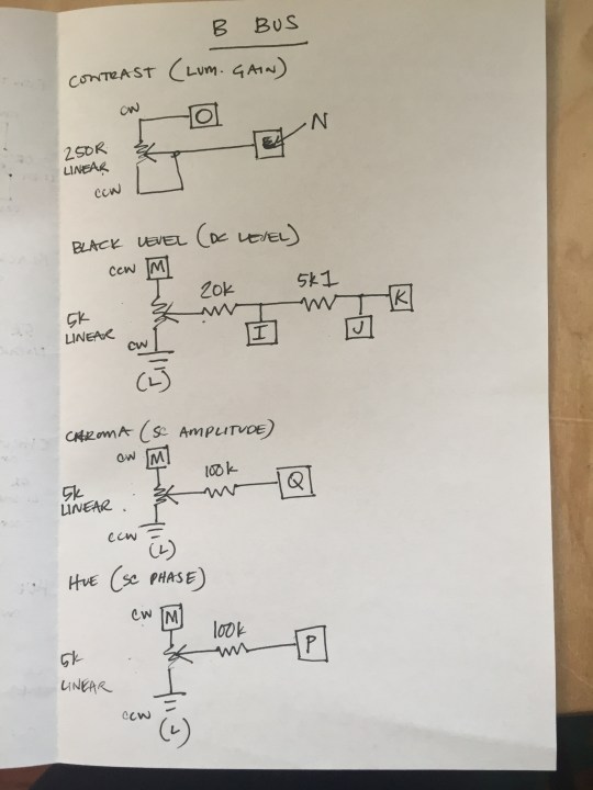
Black level, Chroma & Hue pots are 5k linear, center detent.
Contrast pot is 250Ω linear, center detent.
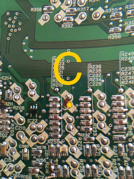
Analog Board JRZMX50P2C connection points (underside of the board):
A: Tiny hole to the left of the R211 marking
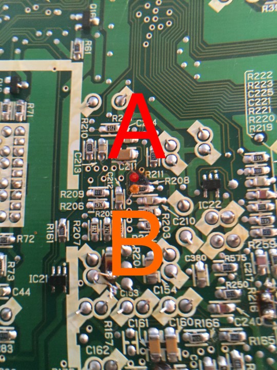
C: Pin to the right of R223
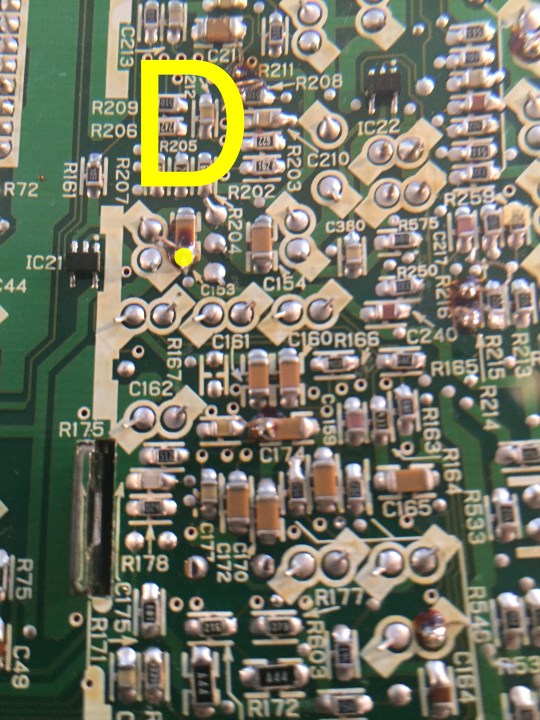
D: Lower leg of C153
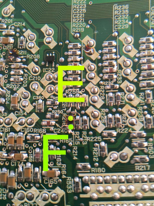
E: Pad for upper leg of r214
F: Pad for lower leg of R214
NOTE: R214 has been removed.
G: Left leg of C174
H: Pin above C164

I: Tiny hole to the left of the R302 marking
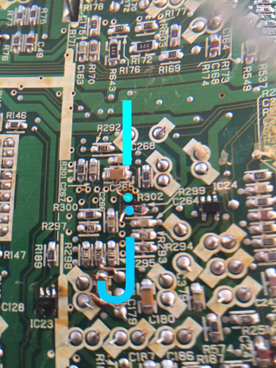
K: Pin to the right of C250

L: Upper leg of C179 (ground)
M: Lower leg of C179

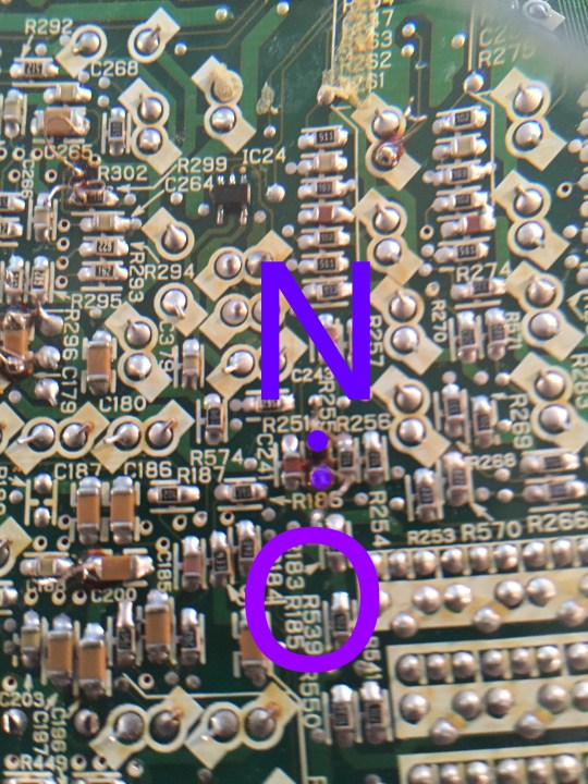
N: Pad for upper leg of R255
O: Pad for lower leg of R255
NOTE: R255 has been removed.
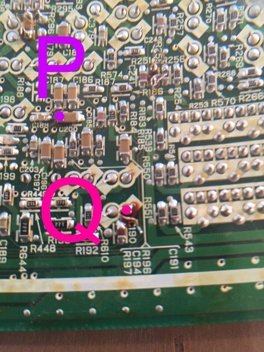
P: Left leg of C200
Q: Pin above C190 marking
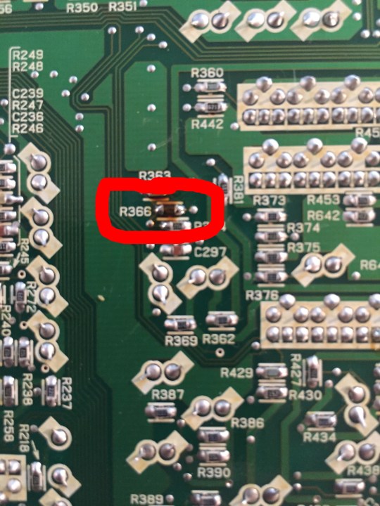
43.2kΩ SMD resistors have been placed on the previously empty pads at R314 & R366:

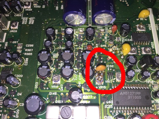
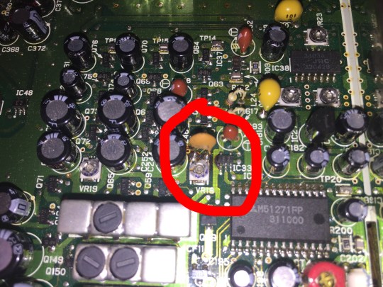
On the top of the analog board, 270 pF ceramic capacitors have been added across the top two legs of VR15 & VR18 (hint: those are the ABUS and BBUS Y-gain trimmers, smoothing maybe?)
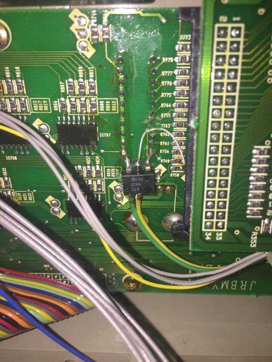
This chip (below) is connected to the level pot for the BC generator.
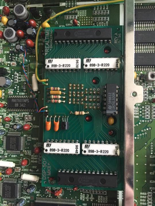
I found this entire daughterboard living in the digital shield. There go my dreams of cloning this thing! Red wire is going to 5v, blue to ground (if memory serves). Green and yellow go to the IC in the above pic.
edit: after hearing from Bob, I learned that this daughterboard is for the DSK 50 mod that allows the DSK to be used as Luma key when color bars are selected as the fill matte. Full documentation is linked at the top of this page.
 [END]
[END]
