
VGA4EVA Build Guide
Welcome to the world of hacky video signal generation!
There are three options for parts depending on how you’re going to build.
Click on the link below that describes your build to automatically download a Word document of the parts list for you (check your downloads folder after you click).
The lists contain “Quick Order” instructions for painless automated ordering from Tayda.com.
I’m going to build both VGA4EVA and CHA/v 3.0 (only order this list once if you’re building both)
I’m going to build VGA4EVA to use with an old version of the CHA/V
I’m going to build VGA4EVA as a standalone device — no CHA/Vs
If you’re building VGA4EVA along with a CHA/V 3.0, I’d recommend starting with VGA4EVA. It’s the easier of the two builds, and it can do a few things without the CHA/V. Once it’s up and running, you can add the CHA/V.
OK, here we go!
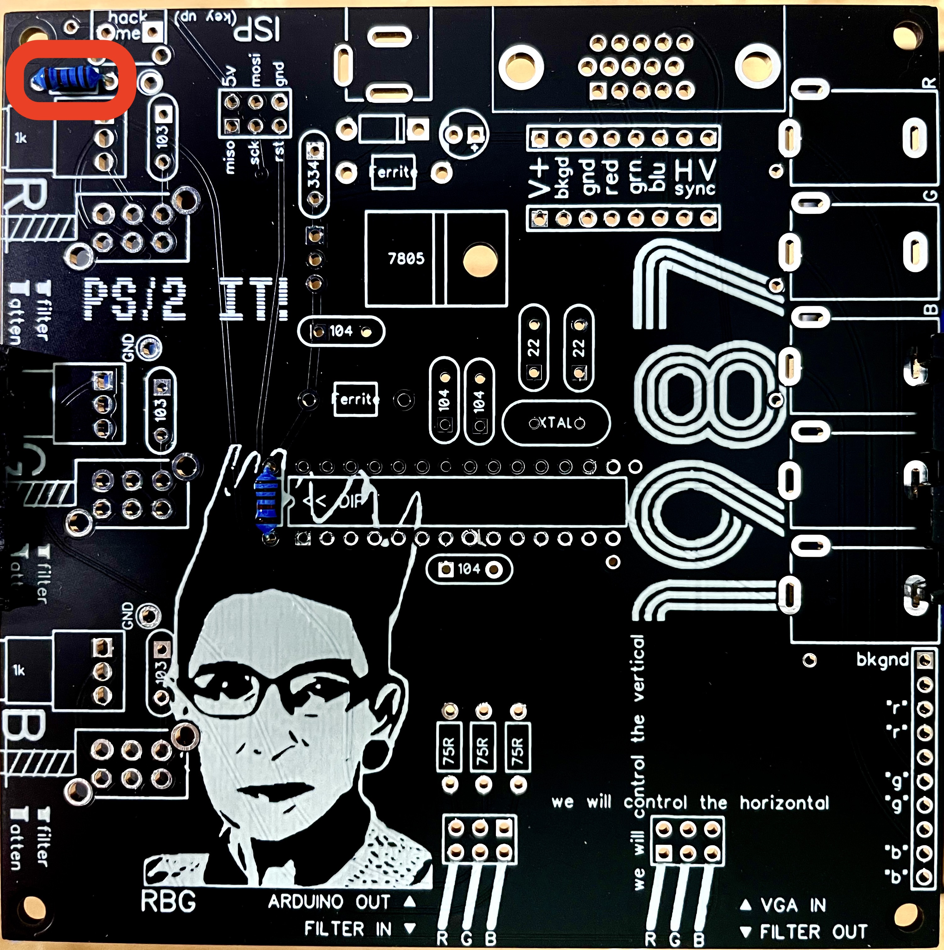
Step 1: Solder in the 10k resistor.

Resistors aren’t “polar”, so there isn’t a right or wrong direction to place them in. All the parts, including the resistors should be smushed flat up against the board. Once it’s placed in the board, you might find it helpful to bend the legs out to an angle so it doesn’t fall out when you flip the board over. Some people like to solder from the top of the board, which is ok in most cases, but doesn’t work with certain parts.
Note: We’re only using one 10k resistor. If you ordered from Tayda there will be 9 left, as 10 is the minimum order. Fortunately they cost $0.012 apiece. There will be some leftover resistors for almost every value in this project. Start a collection!
Step 2: (optional) Solder in the 1k resistor.
The 1k resistor is a pull-up resistor for the “hack-me” tact button. The button doesn’t have any code to support it at the moment (so it doesn’t do anything) but it might at some point in the future, so I added a place for one. You might as well just solder it in now.
Step 3: Solder in three 75ohm (75R) resistors.
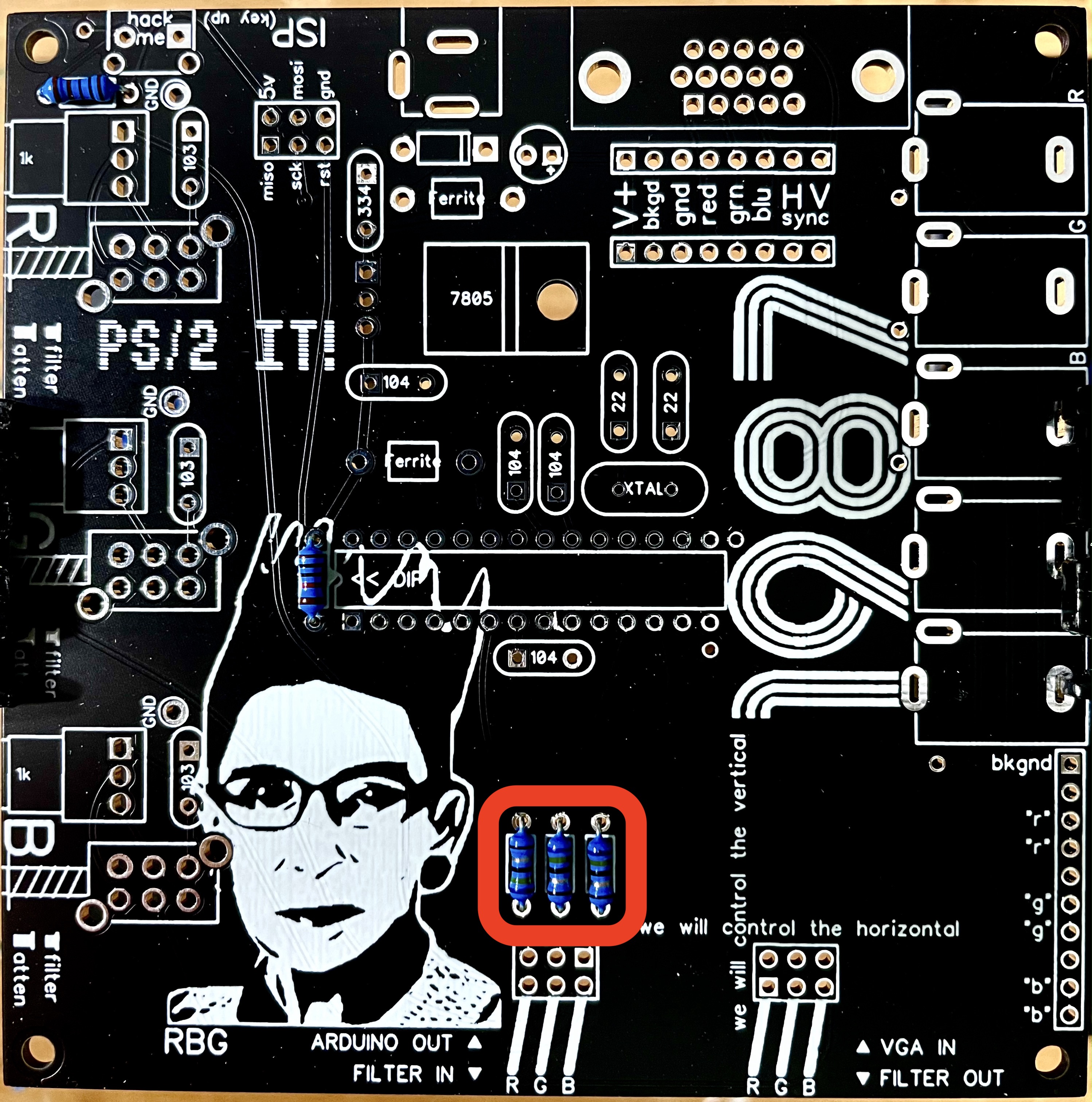
Later on, we’re going to steal the ATMega328 microcontroller chip from the Arduino and these resistors will connect red, green, and blue generated on the chip to points that we can patch. Save some scrap resistor legs for later. We’re going to use three of them for something weird.
Step 4: Solder in the 1N4001 rectifier diode. Diodes are “polar”, meaning there’s a right way and a wrong way to install them. Line up the stripe on the diode with the stripe in the picture and you’re good to go.
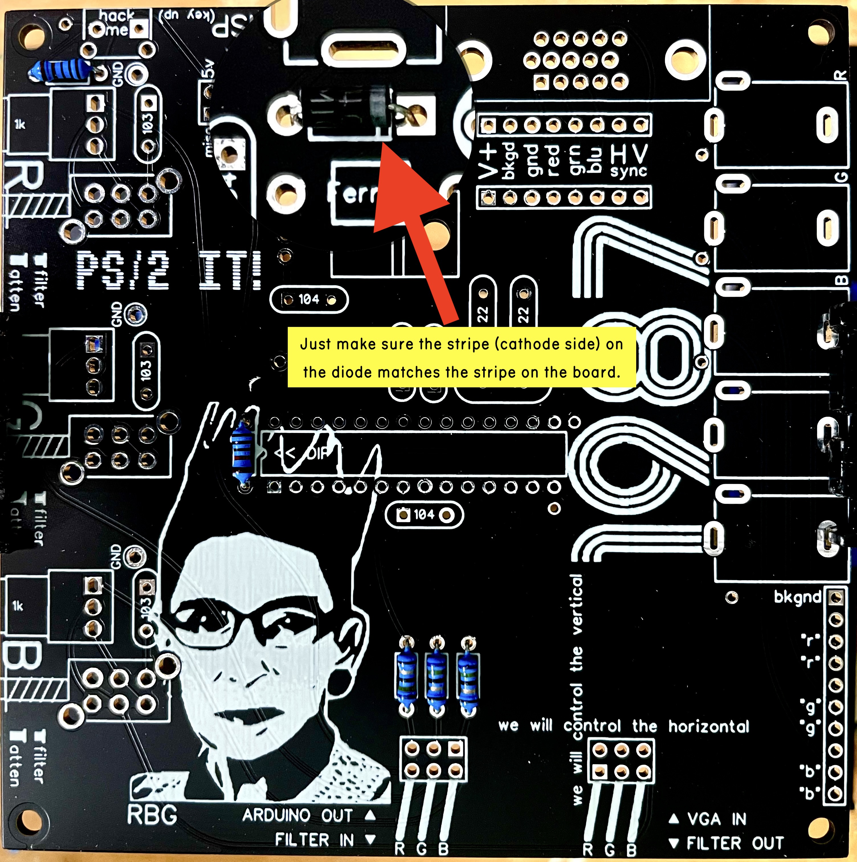
Rectifier diodes are like one-way valves that only allow current to flow from the anode to the cathode. In this circuit, the 4001 is being used to protect the power inlet from reverse polarity. If you accidentally use a center negative power supply instead of center positive, the 4001 will theoretically block the negative current, protecting the chip, electrolytic capacitor, and possibly the voltage regulator from being destroyed.
Step 5: Solder in the two ferrite beads (non-polar).
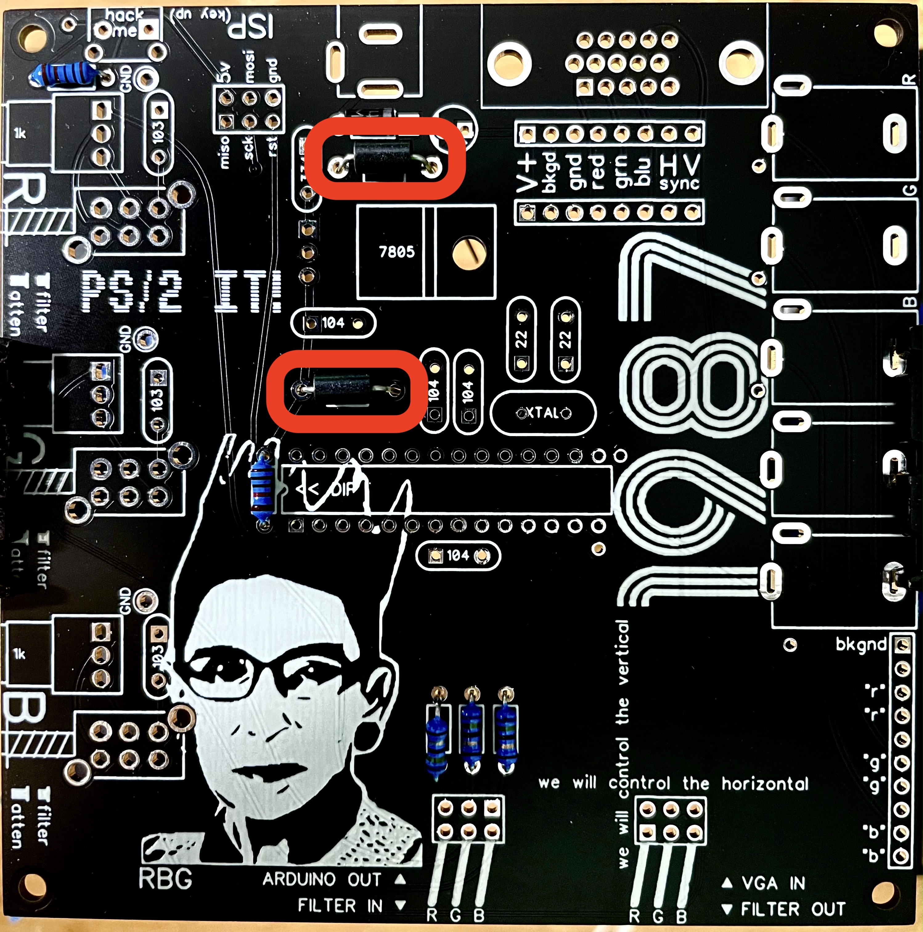
Ferrite beads filter high-frequency noise from the power supply. Video systems are particularly susceptible to noise issues because they use higher frequencies than audio. Also, If the power supply is noisy, we can see the noise in the signal. If you notice tiny ripples along the edges of lines, yep, noise. A high quality video synthesizer needs either a beefy old linear power supply or a modern switching supply that’s been specifically built for video. These ferrite beads are the absolute minimum effort to keep the ATMega328 happy and make a nominal effort to filter some power noise out of the signal. CHA/V stuff is such a hacky, noisy mess that it’s possible they won’t do much anyway. We’ll just sacrifice these two to the video gods for posterity.
Step 6: Solder in the 16.000 MHz crystal (non-polar).
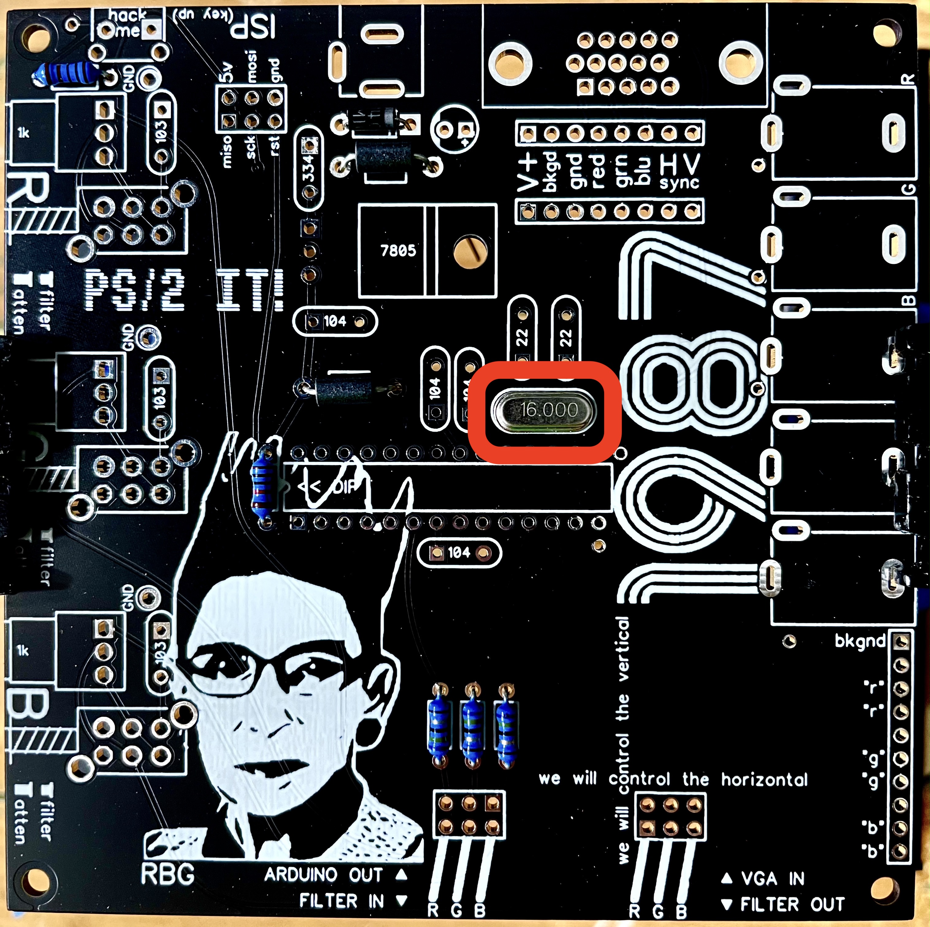
I’m not going to try to explain how a crystal oscillator works, but it mysteriously vibrates at 16MHz, which is the clock speed the ATMega328 needs for this project. I wouldn’t anger it if I were you.
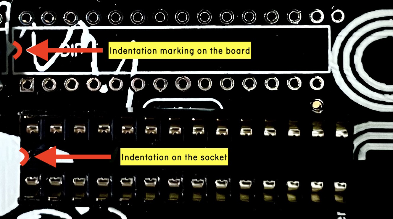
Step 7: Place the IC socket on the board, but don’t solder it in yet. The socket has a little indentation on one end that tells us which way to place it. If you happen to solder it in backwards, it doesn’t matter as long as you don’t also put the chip in backwards. Again, don’t solder it in just yet.
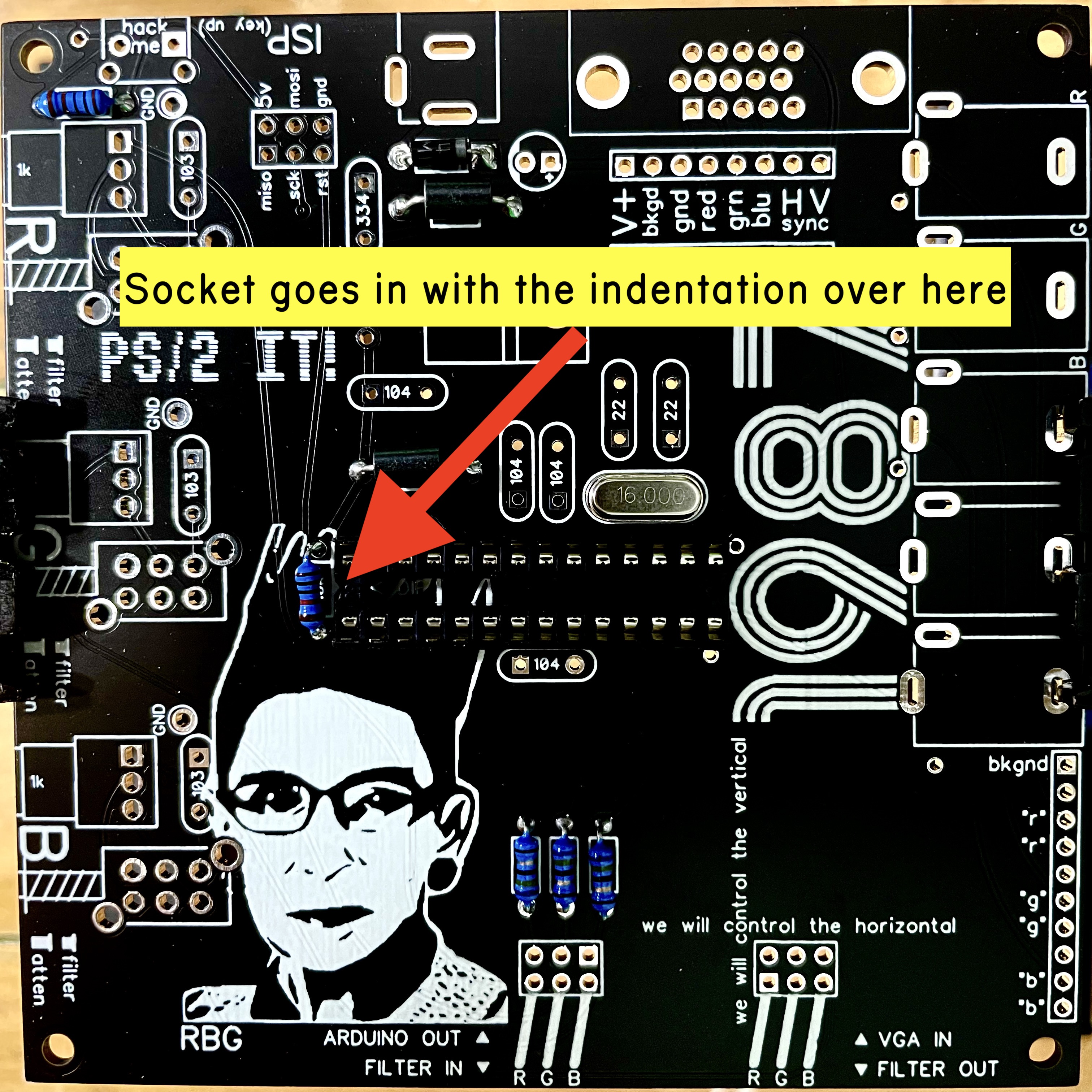
The socket will eventually become a home-away from home for the ATMega328 chip, effectively turning VGA4EVA into an Arduino for hacky video synthesis. Sockets let us swap chips easily, and they also keep us from overheating chips during soldering. They aren’t necessary in most cases, but advisable and helpful here.
Step 8: Flip the board over and tack one leg of the IC socket.
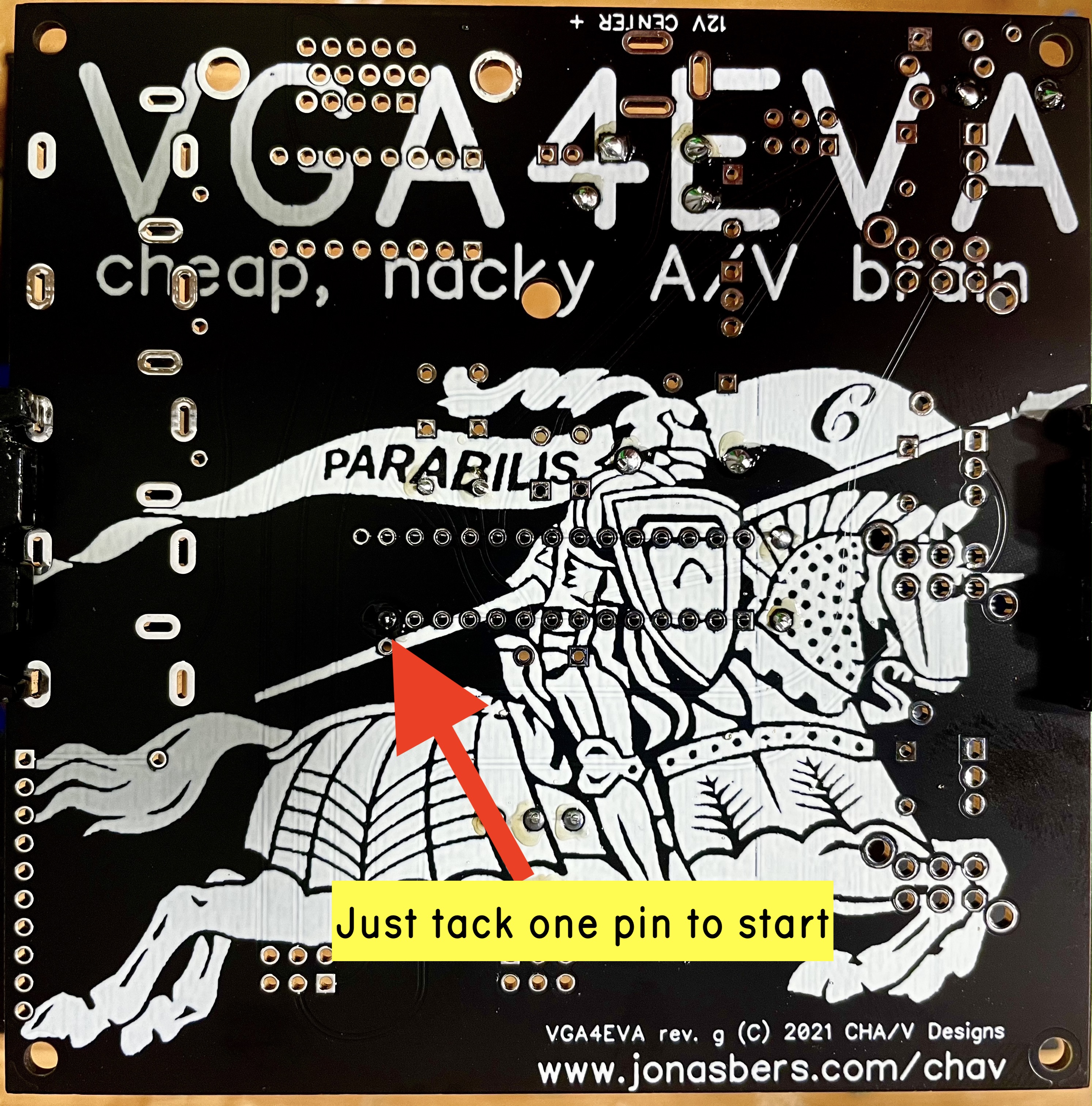
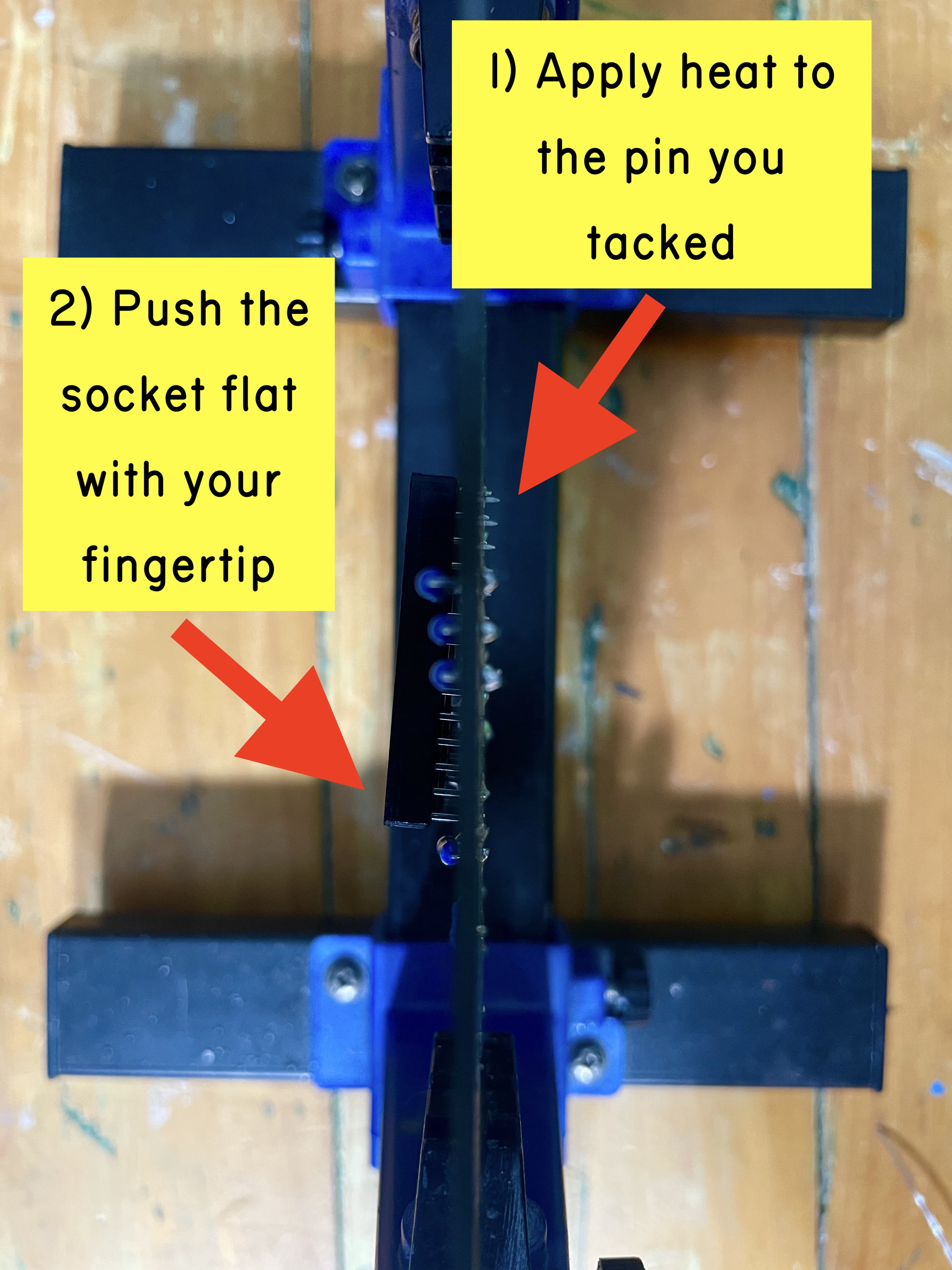
Step 9: If the socket is nice and flat against the board, you can go ahead and solder the rest of the pins. If not, we’re going to use a technique that we’ll also use later on the pin headers and switches. Heat the pin that you tacked before and at the same time, gently press down on the socket with your finger until it’s flat against the board. Keep in mind which pin you’re heating and keep your finger away from that pin — it will be hot enough to burn you if you touch it.
Yes,there are lots of pins on the socket. This is good practice for the headers and the VGA socket that are coming later.
Step 10: Drop the L7805 voltage regulator into the board, and then fold it down. Once it’s reasonably settled in the board, you can solder it.
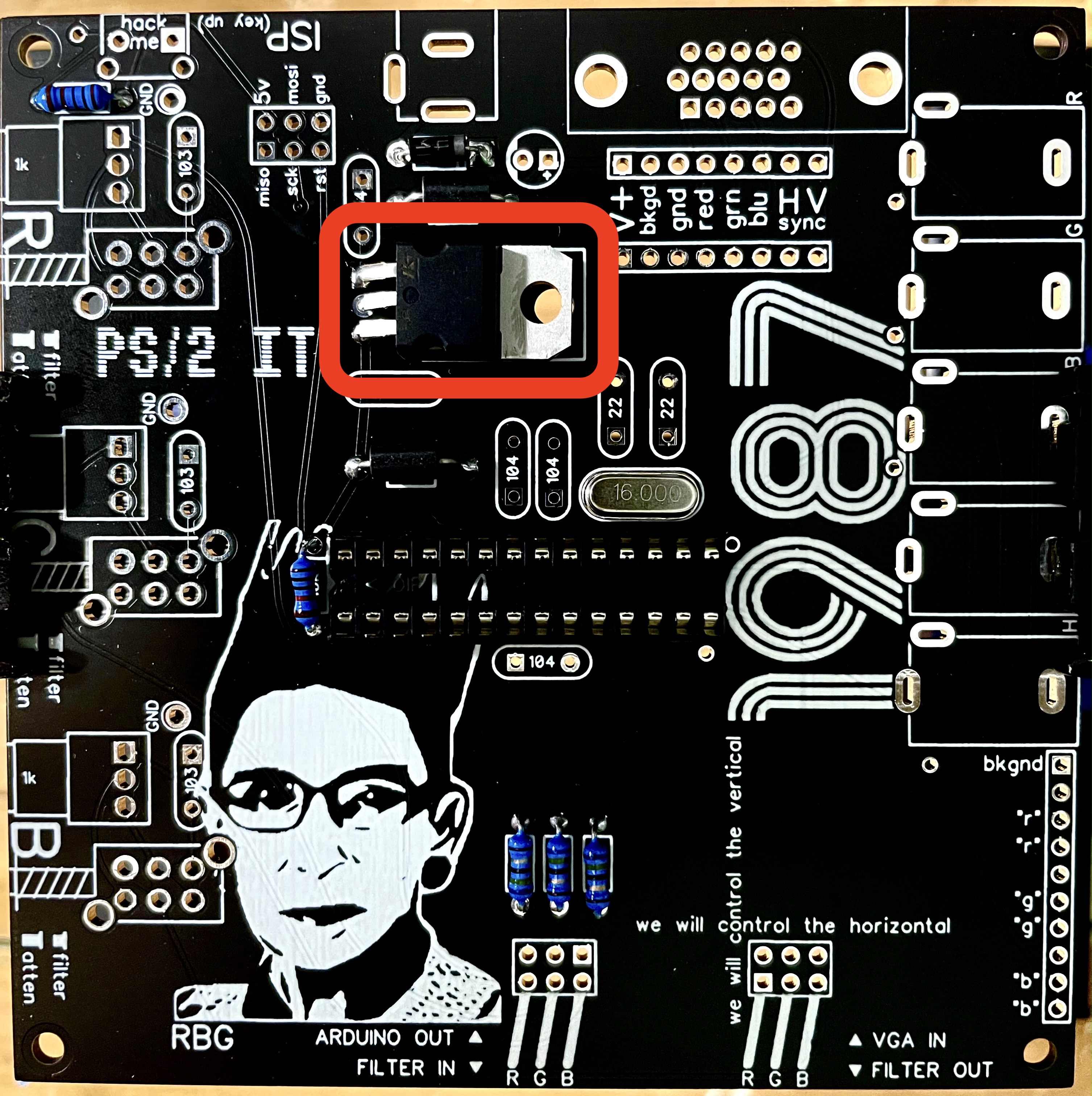
Voltage regulators output a steady constant voltage. In this case, the 7805 is taking +12v DC from the wall-wart and converting it to a nice steady +5v DC for the ATMega328. LM78xx voltage regulators come in a variety of flavors. The last two digits tell us the voltage output. LM7805 = 5v output. LM7812 = 12v output, etc. There are also LM79xx regulators for a negative voltage input and output.
The 7805 is capable of handling a 7-35 volt input, although it will generate some heat with higher voltages and when it’s feeding power hungry devices. The hole at the top is for connecting a heat sink (some metal to dissipate the heat), but it’s not necessary at 12v with the small amount of power we’re using here. The ATMega328 will just nibble on it and it should stay cool.
We’re using a regulator here instead of a 5v wall supply for two reasons. 1) the CHA/V needs 12v, and we’re just using one power input for both devices. 2) the ATMega328 will be unhappy with any power fluctuations that can happen with a wall supply, so we’re much better off knocking the 12v down to 5v and getting a more reliable 5v supply.
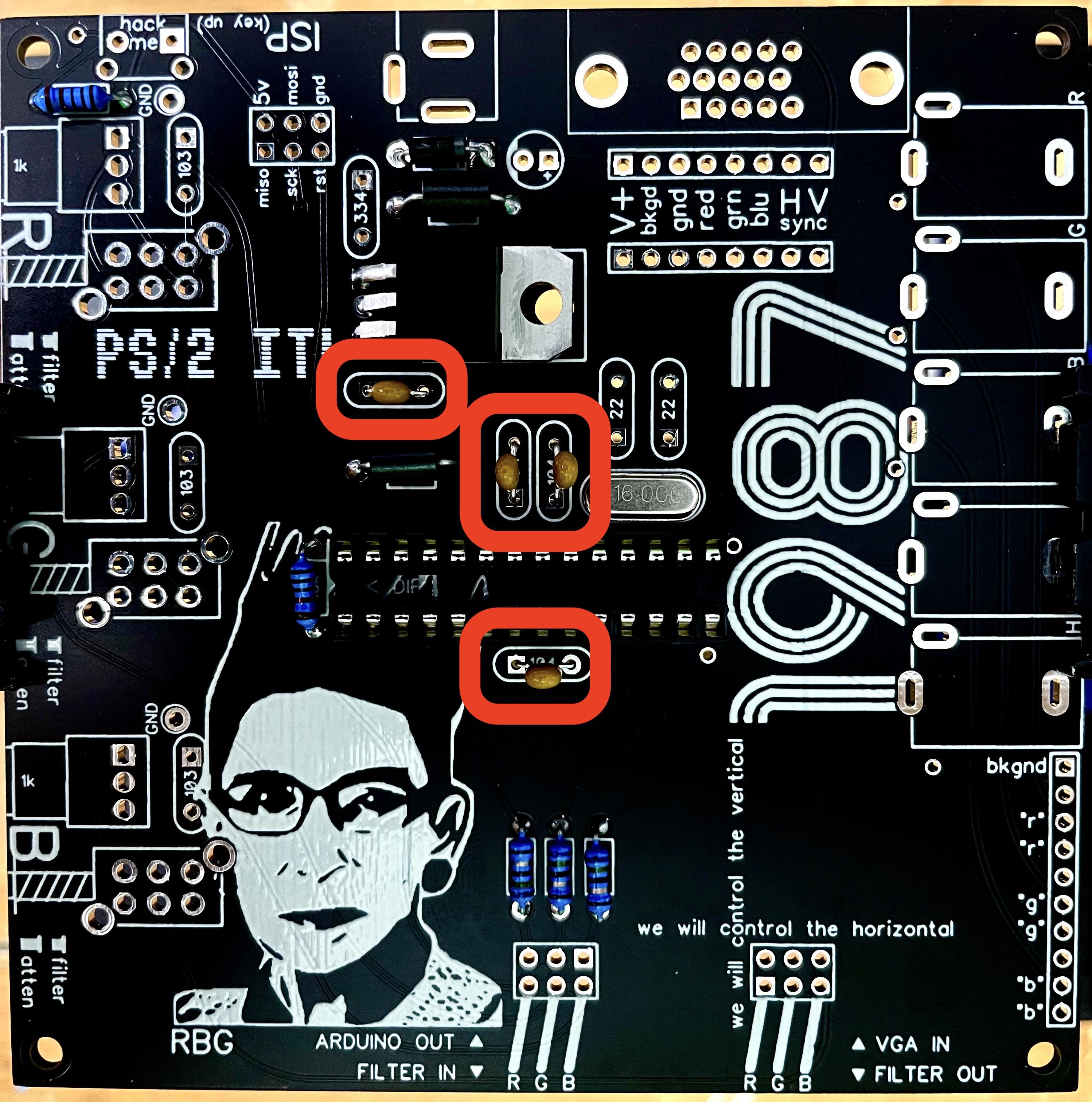
Step 11: Time for capacitors! Let’s start with the four 0.1uF. All of the little yellow MLCC caps are non-polar.
In tiny writing, the 0.1uF caps are labeled 104. You can Google capacitor codes if you’re interested in learning to read them, but for the sake of simplicity, the board is just labeled with the codes. 104 on the cap, 104 on the board. Easy.
Some of the caps will have kinked legs to match the hole spacing on the board. That’s on purpose — they don’t need to be bent or forced flat. Just drop them in place and solder them in.
There will be lots of 0.1uF caps left for the CHA/V. Put ‘em back in the bag when you’re done.
This is a pretty common capacitor value used for “decoupling” chips. In that use, they’re placed right next to the power input pins on a chip, with one end connected to the power pin and the other end going to ground. That way, the capacitor can act like a tiny battery, filtering out voltage spikes that would otherwise affect the operation of the chip. On VGA4EVA, there’s one 0.1uF decoupling cap on the output of the 7805 and three on the ATMega328 power pins.
Step 12: Solder in the 0.33uF cap (334). This one is on the input of the 7805.

Step 13: Solder in the two 22pF caps (22).

These two are connected to the legs of the crystal. By some mysterious force, they help the crystal resonate at 16MHz.
Step 14: Solder in the three 0.01uF caps (103). There should be some left if you’re building a CHA/V. Back in the bag.
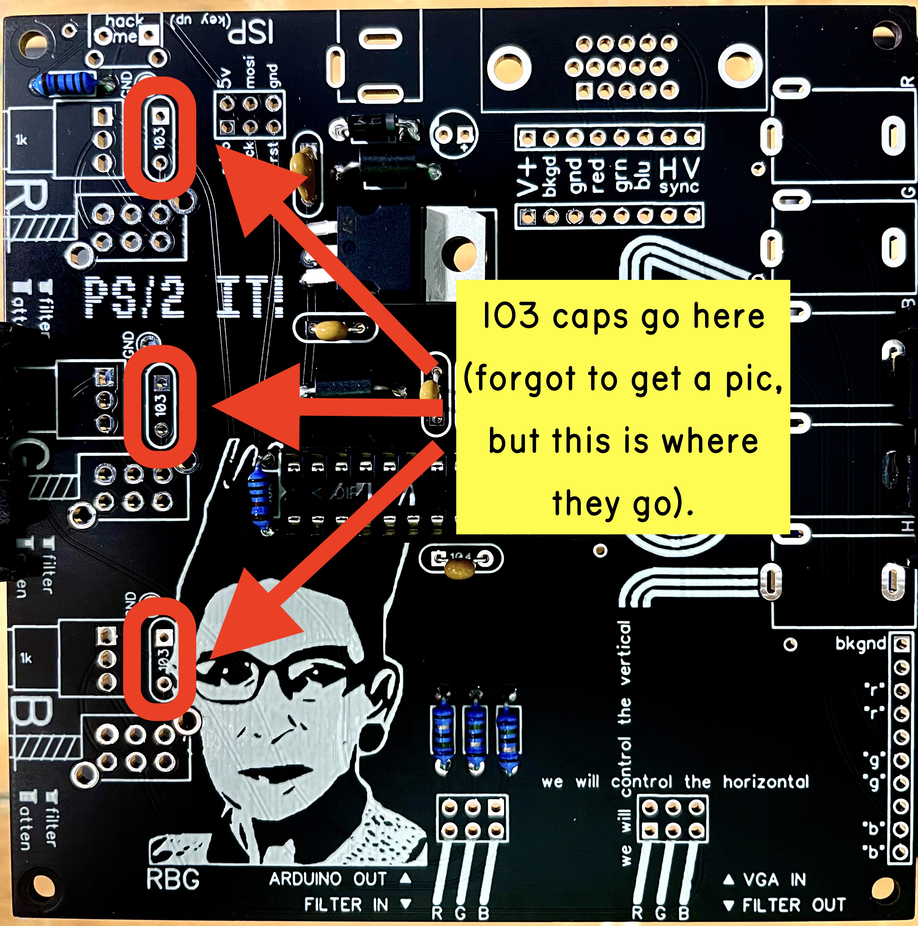
These caps are doing something a little more interesting. They’re using the filtery behavior of capacitors to filter the red, green, and blue elements of the video signal. More on this later.
Step 15: Let’s get that 2×40 right angle header in. We need to cut three 2×3 sections off. This whole operation is kind of a pain, but the video should help a lot.
The two headers at the bottom will be for patching, and the one at the top is for programming if you have a programmer. Btw, if you have a programmer, you might want to connect it (unpowered) while you’re soldering the header in to make sure it fits. If you don’t have a programmer, but might get one at one point, you might want to hold off on the programmer header. If you use jumpers for place holders while you solder the programmer header in like I did in the video, MAKE SURE YOU TAKE THEM OFF before you power up the device.
Don’t worry if you mess up some of the header cuts or if the pieces go flying into the forth dimension. There are 40 rows and we only need to get three sets of three. The rest is extra. It can be useful if you want to do some Arduino experiments using the innie/innie patch cables, so hang on to it.
Step 16: Push buttons! These little switches are hilarious. I just chose them because they’re the only 2P2T switches that Tayda stocks, but after getting to know them I was endeared to their quirky little selves. We need to trim their mounting tabs off before we can use them though.
Check the video about that:
and then watch this:
Step 17: Pots! Grab three 1k pots and fish some scrap resistor legs out of the garbage if you forgot to save some. If you’re building a CHA/V there should be two 1k pots left. The pots are going on the board in a made-up way. I don’t mention it in the video, but it’s important that the pots are pushed down all the way to the board, and they’re aligned correctly. We’re making a CHA/V sandwich with the other PCB, and it won’t fit together properly if the pots are askew. Also, if you’re getting solder bridges on the pot legs, they’re easier to remove once the leads are clipped. Watch:
The pots, along with the 0.01uF caps, form three RC (resistor capacitor) passive low-pass filters that you can use to mess with the video signal. Filters like this smear or blur sharp edges. Just like the decoupling caps filter out voltage spikes for power, our RC filter will filter out sharp edges in the video, but these can be adjusted with the potentiometers. More filter = softer edges, less filter = sharper edges.
Step 18: Fun part! Solder in the five mono jacks. If you’re building VGA4EVA as an add-on to a previously built CHA/V 2.0, just do the H&V jacks.

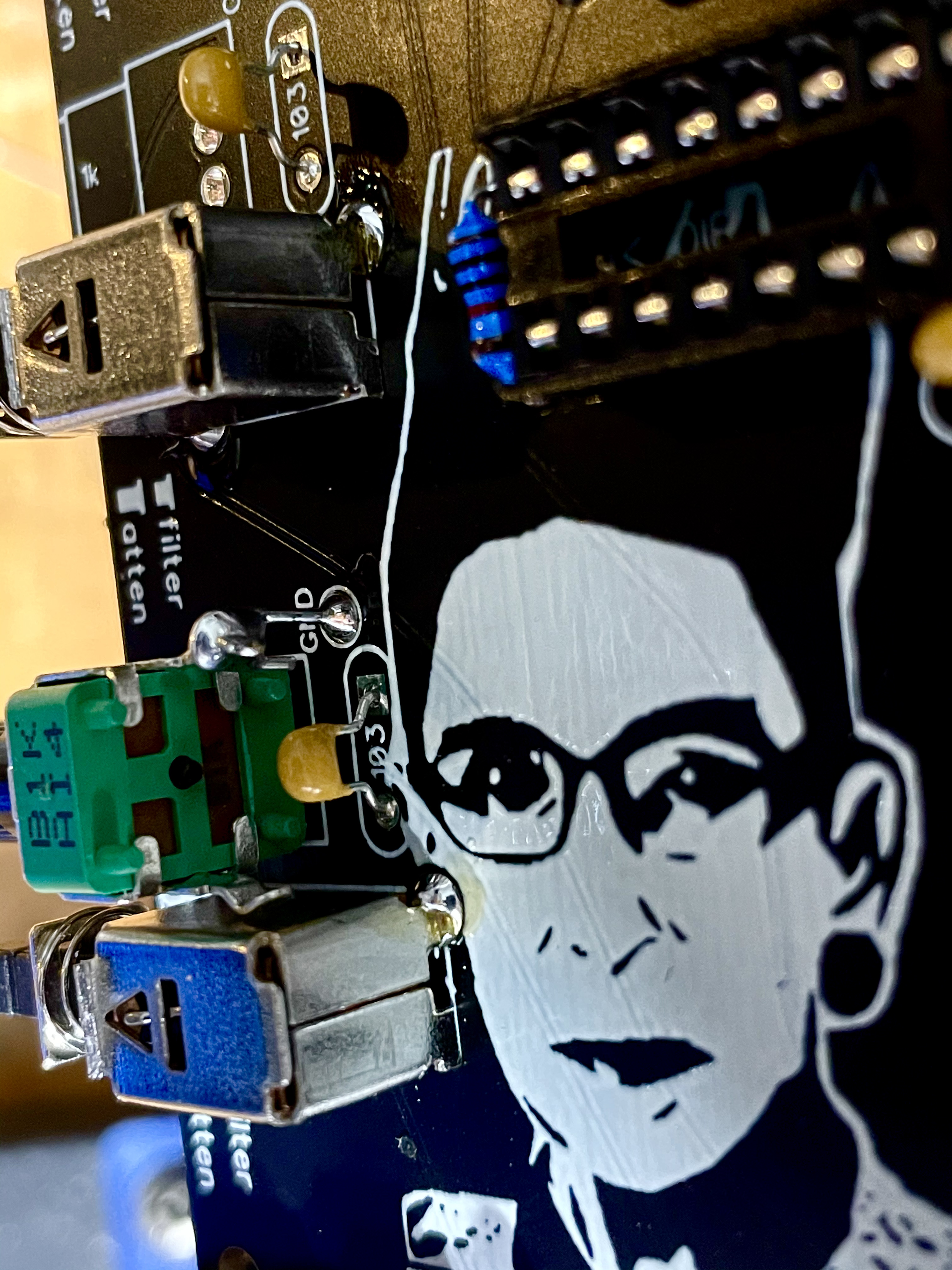
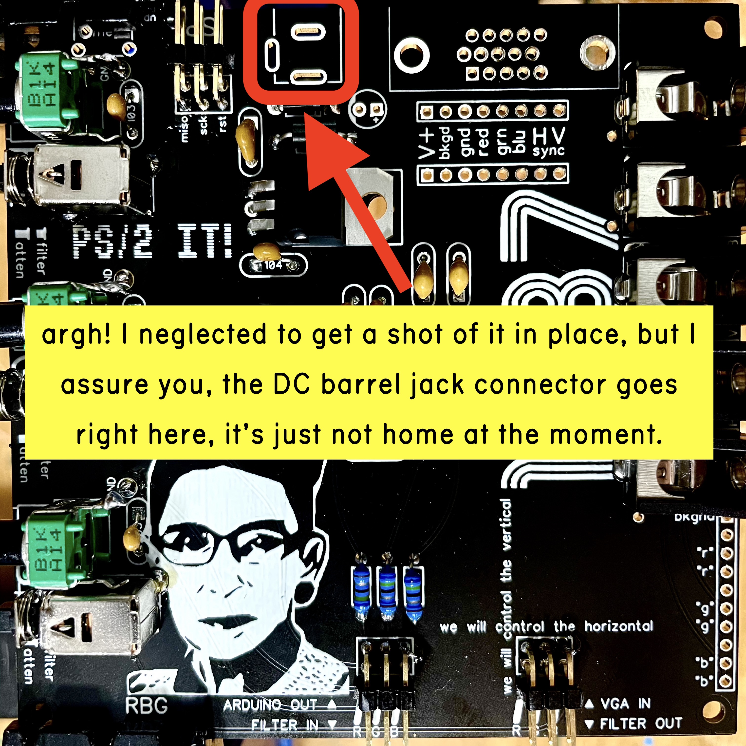
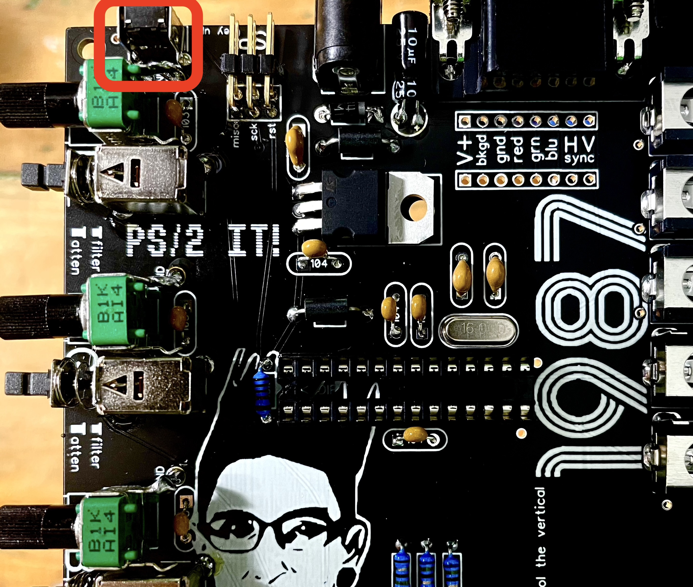
Step 19: Solder in the DC power jack. Almost done!
Step 20: OK. This is probably the most difficult step. If you’re tired, it’s a good time to take a break. If you’re a beginner and this project has been a struggle so far, you might want to stop for the day and come back to this fresh tomorrow. If you’ve made it this far, you have the skills the for this step, but you need to be sharp. It’s time to solder in the VGA jack. Go for it if you know what you’re doing. Watch this vid if you’re nervous or if you run into any trouble:
Step 21: Grab the 10uF electrolytic capacitor. THIS ONE IS POLARIZED, and it will be pretty “exciting” if you put it in backwards (it’ll explode when you plug the device in). Make sure the stripe on the capacitor (the negative lead) matches the stripe on the board. Drop it into the board, and carefully fold it down into the little hallway between the DC and VGA jacks. It’ll knock its head on the CHA/V if you don’t fold it down. If that doesn’t make sense, watch this:
Step 22: (optional) Solder in the “hack me” tact switch. Again, this doesn’t do anything at the moment. It’ll probably find a use at some point though. Feel free to skip this step if you’d like.
Excellent!! 99% of the soldering on VGA4EVA is done. Now is a good time to let your soldering iron cool down, get some fresh air, and head over to the VGA4EVA Programming Guide. Once that’s done, you can play around with it as-is, or get started on the CHA/V Build which will show you how to connect the two devices. Links for all of that stuff is back on the Build Guides page, which includes a guide for connecting VGA4EVA to old CHA/V versions too.
The video below video talks about some optional things that will mostly be relevant for people who want to do some hacking or are building VGA4EVA as a standalone (no-CHA/V) device. There are some pads for hardwiring things, and this is mostly about that:
